You only get one chance to ‘get it right’ when you’re doing it live, which is why you should go with a media producer who has the experience, confidence and knowledge of live production. Whether you’re in a studio, or outside exposed to the climate. Whether it’s a simple single camera shoot or the full multiple moving cameras with on screen graphics shooting match… We’re here to help you get in CTRL of your production
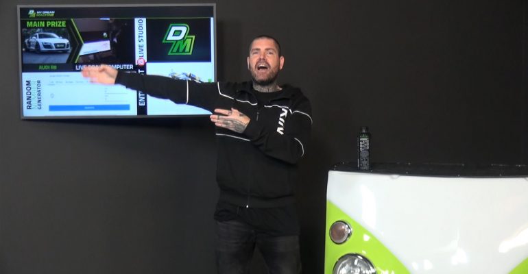
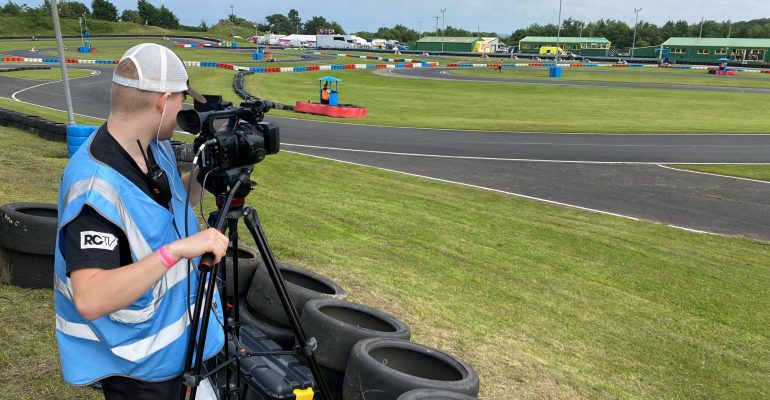
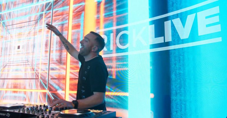
From the studio to the seaside, live video broadcasting relies on experience, equipment and nerves of steel!
Why Choose CTRL
There are many media companies out there, so why choose CTRL? We’re experienced, ready and focused on giving you an amazing ROI. But most of all a production that will delight!
Fair prices
Live content has a reputation of being extraordinarily expensive, but it doesn’t have to be. We work with every customer to find the right level of production to fit their needs – and their budget.
Eye for details
A myriad of tiny details make a live production go right – and we know exactly what to look for… and when. From the size of on-screen text to the location of lights or a moving camera, our team are on the scene with a reputation for making it perfect.
Great support
Live productions require a huge amount of experience and planning, and we’ll be with you all the way from the planning stages to the end credits, to make sure everything goes off without a hitch.
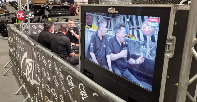
The technical proficiency to bring people together
Tell me more about live streaming
Live broadcasts, or ‘live streaming’, relies on a balance of technical knowlege, quality equipment and quick creative thinking. Detailed planning and guidance invested beforehand avoids common issues seen with less experienced or ill-equipped broadcasters.
CTRL Media can give you:
- Complete live streaming event consultancy
- Advice for building a creative brief to maximise engagement
- Support and guidance on building the best possible broadcast
- Advice on building viewership before and after the live event
- Development of plans to invigorate and engage your audience
- Post event evaluation and analysis
- Post-event editing for repurposing on social media
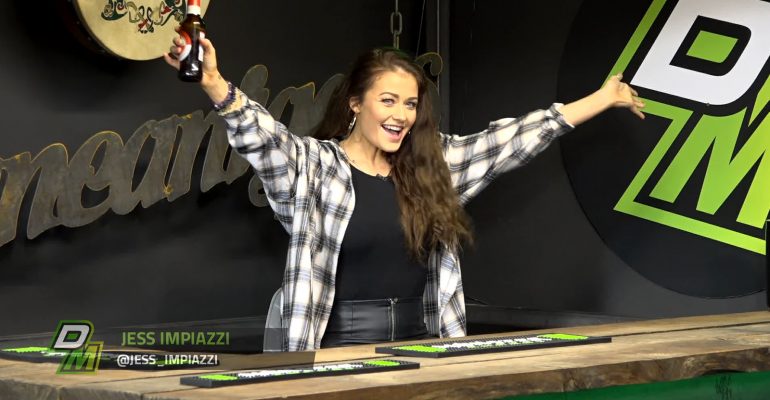
Adaptable, knowledgeable, confident... and even fun!
FAQ
We’re happy to answer any questions you may have – just get in touch, or have a look at the most commonly asked questions we get about our live broadcasting services.
Smallest: A closed-captioned in-car camera footage to a handful of billionaires and royals. Read more about this event here!
Largest: A Live World Championship Racing Event from Spain to over 20,000 fans around the world, featuring live competition coverage with multiple moving and static cameras, multiple commentators, intro & outro video, daily produced content, live interviews, plus social media including video, posts, photos and more
We have broadcast events from The Philippines to Australia and USA to Croatia – we definitely have you covered! All of our equipment is portable and suited for remote work, with every member of the team well-versed in international travel. Plus Carnets and all that fun paperwork stuff taken care of
It is very easy to share live video with friends and family members these days, however most instances in a professional environment will need good equipment and technical know-how. Consider if you’ll want multiple cameras to follow a speaker as well as the crowd or any other action, and also if you’ll need to capture high quality sound. A professional technical setup can make use of redundant broadcasting signals so every second of action is covered, plus have the ability to catch interviews and anything else you’d associate with live broadcasting.
Definitely! We are a 360 full service media agency, versed in everything required to get as many viewers as possible to watch. We can provide event planning and promotions, social media posts during the event itself, and post-production of footage for highly produced content highlights.
Because there is such a wide array of possible event coverage, it’s simply not feasible to say how much live broadcasting will cost for your event without discussing your needs. Please get in touch here or send us an email at hello@ctrl360.media and we’ll be happy to discuss everything you need to make your broadcast the best it can possibly be!
Let’s talk today
If you want to start a new project, we invite you to get in touch with us.